
A Method for Synchronous Dataflow Retiming
2017 IEEE First Ukraine Conference on Electrical and Computer Engineering (UKRCON)
Anatolij Sergiyenko, Anastasia Serhienko, Andrij Simonenko
Computer Engineering Dept.
Igor Sikorsky Kyiv Polytechnic Institute
Kyiv, Ukraine
aser@comsys.kpi.ua
Abstract. A method of retiming the spatial synchronous dataflow graph (SDF) is proposed, which is based on the SDF representation in the multidimensional space. The dimensions of this space are spatial coordinate of the processing unit, coordinate of the operator firing and operator type. At the first stage of the datapath synthesis, the operator nodes are placed in the space according to a set of rules providing the minimum hardware volume and minimum clock period. At the second stage of the synthesis this spatial SDF is balanced and optimized providing the minimum register and multiplexor number in the resulting datapath. The resulting spatial SDF is described by VHDL language and is modeled and compiled using CAD tools.
Keywords—retiming; SDF, scheduling, pipelining, folding, datapath, FPGA, DSP
I. INTRODUCTION
The modern high-performance computers operate with high clock frequencies that are up to several GHz, thanks to the pipelined mode of data processing and transmission. There are various methods for the design and optimization of the pipelined datapaths. These methods are based on the structural synthesis of the datapath, describing it at the register transfer level and further conversion to the gate level. The basis of many methods is a representation of the algorithm as a synchronous dataflow graph (SDF) and its transformation [1]. Such SDF optimization techniques as retiming, folding, unfolding and pipelining, are widely used in microelectronics [2], real-time system programming [3], and design of digital signal processing (DSP) devices [4]. In this work, a new method of the SDF optimization is proposed, which improves the method of retiming.
II. SDF OPTIMIZATION METHODS By the high-level synthesis of the computer hardware, the cyclically repeated algorithm is represented by SDF. The actor nodes in it correspond to the algorithm operators, and the edges correspond to variables, which are transferred between actors with a delay to the predetermined number of the algorithm cycles. Thus, each actor generates and consumes a number of variables (tokens), which is constant from cycle to cycle [1,5]. The homogeneous and multirate SDFs are distinguished. In multirate SDF, the number of variables, which are consumed and generated by each node for a single cycle may be more than one [5]. For ease of the SDF analysis and mapping, the multirate SDF is usually converted into an equivalent homogeneous SDF [5,6]. Next, only homogeneous SDFs are considered.
SDF is isomorphic to the graph of the computer structure, which performs a predetermined algorithm. The nodes of such a graph correspond to the computing resources like adders, multipliers, processing units (PUs). The edges correspond to the communication lines, and the labels on them are mapped to the registers. Consequently, SDF is a directed graph G = (V, E), representing the computer structure, where v ∈ V represent some logic network with delay of d time units. The edge e ∈ E corresponds to a link and is loaded by w[e] labels, which is equal to the depth of the FIFO buffer.
The minimum duration of the clock cycle Т С is equal to the maximum delay of the signal from one register output to the input of another register, i.e., to the critical path through the adjacent nodes with delays d, for which w[e] = 0. It should be noted, that with such a one-to-one mapping of SDF, the duration of the algorithm cycle Т А coincides with the duration of a clock period, i.e., T A = T C, that in the other algorithm mapping is not respected.
The retiming is such a change of the labels in SDF edges, which does not affect the algorithm results. Usually it is realized as a sequence of elementary retimings, each of them consists of a transferring a group of labels (i.e., registers) from the input edges of some node v to its outputs. After the elementar retiming by moving r[v] registers across the node v, the new weight w'[u, v] of the edge e = (u, v) is calculated by the formula
w’[u,v] = w[u,v] + r[v] − r[u] ≥ 0. (1)
At the same time, the fact that w ≥ 0 for all edges of SDF is the natural condition of the retiming correctness [7]. If between nodes u and v more than one route is found, then a parameter W[u, v] is determined, which is equal to the minimum number of registers in these routes. SDF should not contain any loop, which does not contain a register. This condition is satisfied by the inequality:
W[u, v] + r[v] − r[u] ≥ 1. (2)
To find the optimum retiming, which provides the minimum value of Т C, an integer linear programming problem is solved, which is based on the matrices W and D, and the conditions (1) and (2) [3].
In most cases it is allowed to increase the latent delay of the algorithm and to insert the additional registers on the inputs or outputs of SDF. After retiming such modified SDF, the pipelined network with low value of Т C is achieved. This technique is called as SDF pipelining.
The identifies The retiming opportunities are good for the maximum number W[u, u] of registers in a cycle [9]. To increase this value, SDF is often transformed by increasing the number of registers in all the edges in c times. The resulting SDF performs the original algorithms in parallel, but with a period of c cycles. However, it is possible in this SDF to reduce the duration of the clock period in c times. This method is called as c-slow retiming.
In the work [11] a method is proposed, which provides the theoretical minimum of period T C. The method consists in unfolding SDF, and in minimization of delays of logic functions in the critical path.
III. SDF FOLDING Consider the method of SDF folding, which allows to increase the number of registers in a closed cycles. Due to this method, sets of up to c nodes are selected in SDF. These sets are substituted to the separate nodes. Wherein the data flows in new SDF are directed so that the algorithm is executed with a period of c cycles at the cost of the node sharing.
In general, the method consists in the synthesis of a pipelined computational model, performing the initial SDF. This synthesis contains the stages of resource selection (nodes of PUs), operation scheduling and operation assignment (mapping node sets to nodes of a new SDF).
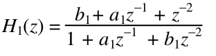
Consider an example of folding SDF, which performs the digital filter algorithm with the frequency response characteristic
H(z) = H 1 (z) + H 2 (z)⋅z −1, (3)
where H 1 (z), H 2 (z) are the characteristics of the second order allpass digital filter:
SDF of this algorithm is shown in Fig.1. The bars in it correspond to the register labels, the circles with a cross and an asterisk represent the nodes of an adder and multiplier respectively. It consists of upper and lower subgraphs, which represent the functions H 1 (z), H 2 (z), respectively. The folded in 2 times SDF is illustrated by Fig.2.
As it is seen in Fig.7, the folded SDF provides in c ≈ 2 times lower hardware costs and the clock period, which is minimized to Т Cс = max(2d A, d M), since one computation cycle of the algorithm requires two clock cycles. Here d A, d M are delays of an adder and a multiplier respectively.
Since in the folded SDF the duration of the clock period Т Cс decreases in c times, it is possible to achieve the following situation. The computer derived from the folded SDF has a period of computing T A, which is equal to the duration of a clock interval T C of the initial SDF, i.e., T A = T C = сТ Сс . In this case, the derived computer has substantially smaller (up to c times) hardware costs.
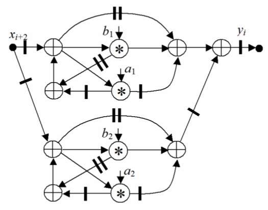
Fig.1. SDF of the filter
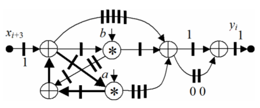
Fig.2. Folded SDF
IV. SDF SHEDULING AND STRUCTURE SYNTHESIS The method of retiming is the most constructive method among the methods under consideration. It allways provides to get the design goal using the proper optimization algorithm, which complexity is comparatively not high. Therefore, the retiming method has been successfully used in many microelectronic CADs. The SDF folding method expands the the retiming effectiveness to the field of structures, in which the processor throughput can be regulated by the selection of the down factor c.
In the methods mentioned above a direct analogy between SDF and the actual pipelined datapath is carried out. In fact, the label on the SDF edge means that the data in the edge must be delayed by w cycles, i.e. on FIFO basis. Replacing these labels by the registers allows us the simplest way to get one of the many correct schedulings of the algorithm execution. The cycle of such a schedule is equal to one clock cycle because of one-to-one mapping. The folded SDF provides the cycle of c clock cycles. Although other possible schedules can take a different number of cycles and different mappings in the structure.
The search for possible schedulings of SDF execution is one of the steps of the pipelined structure synthesis. According to conventional methods, such a synthesis has, in addition to the schedule step, the step of resource selecting, step of assignment of operations to the resources, step of finding the processor structure and its control unit, as well as the step of the resulting structure selection due to the optimization criteria.
The complexity of the multistep structure synthesis is that the various aspects of the synthesis and the development steps are substantially dependent of each other. For example, the hardware costs minimization when resource selecting runs counter to minimizing the cycle time T A during algorithm scheduling. Furthermore, when mapping the algorithm with the down factor c the synthesis problem becomes NP-complete [10]. Therefore, the drawbacks of the multistep synthesis are its complexity and finding not optimum solutions.
Thus, all considered methods provide the limited set of synthesized structures, which are capable of execution of the algorithm with a period of c clock cycles. At the same time, due to the method of SDF folding, all the steps of the structure synthesis have to be implemented in a sequence, i.e., this method has the drawbwbacks mentioned above.
V. METHOD OF SPATIAL SDF MAPPING If the steps of resource selecting, shedule finding and operation assignment are performed in a single combined step, then the structure synthesis is improved and simplified substantially. To find a schedule for SDF means the assignment of the moments of execution time to its nodes. The resulting structure is found by the homomorphic transform of SDF by the gluing the nodes which are executed in a single processor node of the structure graph. Both shedule and structure can be found by the assignment of the respective tags to the nodes. Then the tag contains such parameters as execution time, operator type and PU number.
In the work [11], a method of the pipelined datapath synthesis is proposed, in which SDF is represented in the three dimensional space as a spatial SDF or algorithm configuration K A = (K, D, A), where K is a matrix of node vectors K i representing the operators, D is a matrix of edge vectors D j, which are relevant to the operands, A is an incidence matrix of SDF. In the node vector K i = (k i,s i,t i) T the coordinates k i, s i, t i correspond to the operator type, PU number and the clock cycle. Thus, the vectors K i represent the tags, which code the SDF properties.
The matrix K encodes a correct structure solution, since the matrix D is derived from the equation D = KA, and A is a constant matrix. The search for the optimal solution consists in finding such a matrix K, which minimizes a given effectiveness criterion. It is possible to first set the elements of the matrix D O providing the optimum value of T C, and then the the vectors K i are found from the relation K = D о A о −1, where D о and A о are the matrices of the maximum spanning tree of the spatial SDF.
By searching for effective structural solutions, the following relations are taken into account. Spatial SDF is correct if there are none couple of equal vectors K i, i.e.,
∀ K i,K j (K i ≠ K j, i ≠ j ). (4)
The shedule is correct iff
∀ K i ,K j (k i = k j , s i = s j) ⇒ t i not≡ t j mod с. (5)
The operators of the same type are mapped into PU of the
same type, i.e.,
K i,K j ∈ K p,q (k i = k j = p, s i = s j = q), |K p,q | ≤ с, (6)
where K p,q is a set of vectors of the p-th type, which are mapped into the q-th PU of the p-th type (q = 1,2,… q p max ).
If SDF is cyclical one, then the sum of vectors D jbelonging to the i-th closed cycle must be zero vector, i.e.,
∑ b i,j D j = (0,0,0) T, (7)
where b i,j is an element of the i-th row of the cyclomatic matrix of SDF. The feedback vector D Di = (0,0, –wc) T, which means a delay to w iterations, belongs to this cycle as well.
The effective spatial SDF is derived in two steps. At the first step, the SDF edges are arranged in the three-dimensional space as sets of vectors K i and D j according to the conditions (4) – (7). So, the original spatial SDF is formed. Then the number of PUs is minimized when the requirement |K p,q | → с is satisfied. By this process the vectors D j accept the values (k i,s i,t i) T , t i ≥ 1. This condition provides the spatial SDF, which is equivalent to the retiming with the minimized value of Т С [11]. As a result, both the timetable of the shedule and the outlines of the desired structure are derived in a single synthesis step, allowing to estimate accurately both performance and hardware costs.
At the second step, the SDF balancing is performed. For this, the intermediate delay nodes (registers) are inserted in all its edges except D Dj. As a result, all the edge vectors except D Dj are equal to D j = (a j,b j,1) T or D j = (a j,b j,0) T . The resulting balanced SDF is formed by the node subsets or stages, the distance between them is equal to a clock cycle. This SDF is optimized by the series of the mutual permutations of the node vectors belonging to a single stage. The result is the solution with the minimized number of registers and multiplexers. The optimized spatial SDF is converted to the VHDL description, which is modeled and compiled into the gate level project bu the usual CAD tools. Therefore, the processor structure and its timetable are need not be derived [12].
VI. EXPERIMENTAL RESULTS Consider the retiming and mapping of SDF, which is illustrated by Fig.1. This SDF is transformed by different methods for comparison of their results. The Fig.3 illustrates the spatial SDF after the second step of the synthesis by the method of the spatial SDF mapping. One can see, that the clock interval for this SDF is equal to Т C = max(d A, d M) and achieves the minimum value.
According to spatial SDF, shown in Fig. 3, as well, as to SDF, derived by different methods of optimization, five different filter structures were built. These structures are described in VHDL language and translated into Xilinx Kintex-7 FPGA using the ISE system. For all structures the same project constraints were used.
The results of the five filter structure design are presented in the Table I, in which the hardware cost is equal to the number of logical cells (LCs) S L and multipliers S M. The effectiveness criteria are equal to Q L = S L Т А and Q M = S M Т А, and are equal to the hardware cost per one megahertz of the signal sampling frequency. It is assumed, that the structure, in which the parameters Q L and Q M have lower values, is more preferable.
The table shows that the use of methods of SDF optimization makes possible to improve the quality of the project in 1,1 – 2,5 times. The method of the SDF unfolding provides a structure with a maximum speed due to a substantial increase in hardware expenses. The method of the spatial SDF mapping provides the c-slow as the folding method does, but it reduces substantially the hardware costs S L and the duration of the clock interval T C. In this experiment, this method has provided the best quality of the design solution.
Fig. 3. Spatial SDF
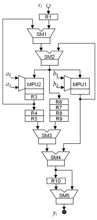
Fig. 4. Resulting filter structure
Table 1. Parameters of synthesized filters
| Method | S L | S M | Т С , ns | Т А , ns | Q L | Q M |
| Pipelining | 259 | 4 | 8,39 | 8,39 | 2,17 | 0,034 |
| Retiming | 212 | 4 | 5,78 | 5,78 | 1,23 | 0,023 |
| Folding | 184 | 2 | 5,43 | 10,86 | 1,99 | 0,022 |
| Unfolding | 510 | 14 | 6,94 | 3,47 | 1,77 | 0,049 |
| Spatial SDF mapping | 144 | 2 | 3,10 | 6,20 | 0,89 | 0,012 |
VII. CONCLUSION The retiming method has been successfully used in microelectronics, FPGA, and programming for more than two decades. This techniques is based on minimizing the signal transmission delay using such pipeline register permutation which does not changes the algorithm functionality. It is particularly important to accomplish such a minimization in the algorithm feedbacks, since in this case the optimization is strictly limited by the number of registers in the routes. Comparing different retiming methods, the high efficiency of the method of spatial SDF retiming is determined. This method provides a maximum ratio of performance to cost in the resulting structures with the feedbacks.
REFERENCES- [1] S. Edwards, L. Lavagno, E.A. Lee, A. Sangiovanny-Vincentelli, “Design of Embedded Systems: Formal Models, Validation, and
Synthesis,” //Proc. IEEE, vol.85, pp.366−390, March 1997. - [2] C. J. Alpert, D. P. Mehta, and S. S. Sapatnekar, eds., Handbook of Algorithms for Physical Design Automation. Auerbach Publications, 2008.
- [3] S. S. Bhattacharyya, P. K. Murthy, E. A. Lee, Software Synthesis from Dataflow Graphs. Kluwer Academic Publ. 1996.
- [4] S. A. Khan, Digital Design of Signal Processing Systems. John Wiley & Sons. 2011.
- [5] E. A. Lee, and D. G. Messerschmitt, “Synchronous data flow,” //Proc. IEEE, vol. 75, pp. 1235-1245, Sept. 1987.
- [6] T. W. O’Neil and E. H. M. Sha, “Retiming synchronous data-flow graphs to reduce execution time,” IEEE Trans. on Signal Processing, vol. 49, pp. 2397 – 2407. Oct. 2001.
- [7] C. E. Leiserson, and J. B. Saxe “Retiming Synchronous Circuitry,” Algorithmica, vol. 6, pp. 5 – 35, 1991.
- [8] K. Ito, K. K. Parhi “Determining the Iteration Bounds of Single-Rate and Multi-Rate Data-Flow Graphs” Proc. IEEE Asia-Pacific Conf. on Circuits and Systems. Taipei, Taiwan, 5-8 Dec 1994, pp. 163 – 168. 1994.
- [9] M. Potkonjak, J. M. Rabaey “Maximally and Arbitrarily Fast Implementation of Linear and Feedback Linear Computations”, //IEEE Trans. On Computer Aided Design of Integrated Circuits and Systems, vol. 19, pp. 30-43, Jan. 2000.
- [10] P. Micheli, U. Lauther, and P. Duzy, “The Systhesis Approach to Digital System Design,” Kluwer Academic Pub. 1992.
- [11] A. Sergiyenko, O. Maslennikow, “Mapping DSP algorithms into FPGA”, //Proc. IEEE Int. Symposium on Parallel Computing in Electrical Engineering, PARELEC’06, Poland: Bialystok, 13-17 Sept., 2006, pp. 208-213, 2006.
- [12] A. M. Sergiyenko, VHDL dlya proektirovaniya vytshislitelnych ustroistv. Kyiv: DiaSoft, 2003. (In Russian).