
High Dynamic Range Video Camera with Elements of the Pattern Recognition
Anatoliy Sergiyenko, Pavlo Serhiienko, and Juriy Zorin
Igor Sikorsky Kyiv Polytechnic Institute
Kyiv, Ukraine
aser@comsys.kpi.ua
Abstract — The issues of development of the system for the high dynamic range (HDR) image processing are considered. The HDR images are often used in the medical image processing and pattern recognition. The modified Retinex method for the HDR image compression is proposed, in which the bilateral filter is substituted by the adaptive filter. This edge-preserving filter is based on the Harris-Laplace detectors, and on the Gauss filter with the regulated kernel. The detector outputs give the information about the local properties of the image and can help to perform the effective pattern recognition. The experimental HDR video camera is built on the base of the Lattice HDR-60 board.
Keywords — HDR; FPGA; Retinex; Bilateral Filter; Feature Extraction.
I. Introduction
In recent times, the high dynamic range (HDR) images and their high-speed computations are widely expanded. The image processing computers are now found in virtually every medical imaging system, including radiography, ultrasound, nuclear medicine, and magnetic resonance imaging systems. Computer analysis of HDR image features has the potential to add objective strength to the interpretation of the expert. It thus becomes possible to improve the diagnostic confidence and accuracy [1].
The most of embedded video cameras do not perform the complex video signal processing but transfer this signal to the computer systems like the clouds by the high-speed networks. It is shown in [2], that extreme amounts of storage and network bandwidth requirements for a high-resolution video surveillance system the cost for deploying a video surveillance management system is rather costly both for a local computer system and for a cloud. Moreover, the remote image processing causes the increased response time, which can be critical in many applications. Therefore, the high-speed preprocessing and even decision making are preferable to be arranged near the image sensor [3].
The HDR image has the pixel bit width up to twenty and more comparing to eight bits of the usual image. Due to this, such an image is effectively used, for example, in X-ray diagnostics because it perceives the information well in the difficult exposition conditions. But with the HDR image processing, it is necessary to solve the problem of the dynamic range compression of the signal without the loss of the readability of the image scene both in illuminated and in darkened areas.
In many works, like [4,5], a video camera system based on the HDR sensor and field programmable gate array (FPGA) is proposed, which performs the HDR compression. But the effectiveness of many of them is far from desired. Besides, the most of them implement only the thinning out the information but not provide making the decision. In this work, an FPGA system is proposed which performs both the HDR image compression and the preliminary image processing for the pattern recognition.
II. Retinex HDR image compression
This problem of the HDR image compression is often solved using the theoretical Retinex model of the scene lighting. According to it, the pixel brightness I of the input image with the coordinates (x, y) is a product
I(x, y) = L(x, y) × R(x, y),
where L(x, y) is the illumination, and R(x,y) is the reflected brightness of the object [6]. According to the Retinex approach, the image I(x,y) is decomposed in a certain way on the components L(x, y), and R(x, y). Then, the component L(x,y) is processed with the dynamic range compression, and in the component R(x,y) the contrast is improved. The processed image components are multiplied to obtain the resulting image I’(x,y).
The brightness components are extracted using the function F(I) of determining the illumination, so that
L(x,y) = F(I); R(x,y) = I(x,y) / F(I);
L’(x,y) = G(L(x,y)); R’(x,y) = b(R(x,y)); (1)
I’(x,y) = L’(x,y) × R’(x,y).
The experience of many authors, for example, in [7], has shown that the effective functions for the compression and the contrast improvement are
Γ(y) = KMo(y / KM) γ(1+ y/KM); (2)
β(y) = (1 + e-b × log y)-1 + 0.5, (3)
where KM, KMo are the dynamic ranges of the input and output signals, γ, b are manually adjusted ratios. The data flow graph of the HDR compression algorithm is shown in Fig.1. The function S in it implements additional scaling and truncation of the image.
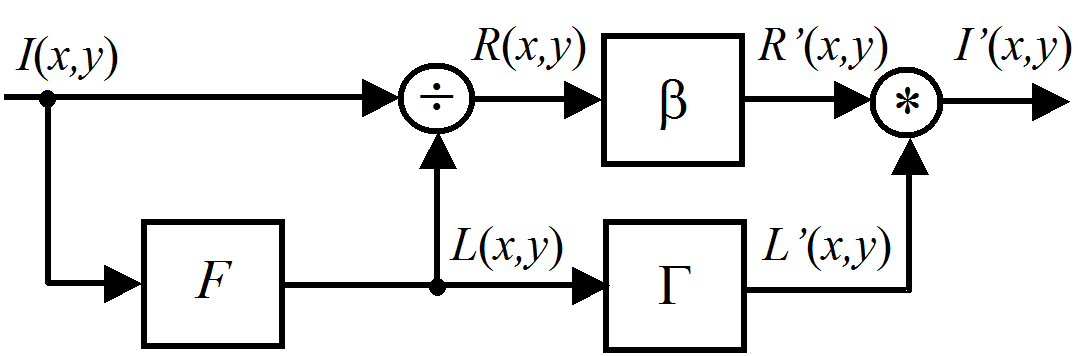
Fig.1. Retinex HDR compression algorithm
The illumination function F(I) in the simple case is a function of a two-dimensional low-pass filter (LPF). But when such a function is used, the artifacts appear in the resulting image in the form of a halo around the object boundaries. To prevent this, the function F(I) should preserve the edges of the image. The most effective function of F(I) is the function of the bilinear filter. The LPF kernel WΩ of this filter varies adaptively depending on the local nature of the image. Such a filter is calculated by the formula:
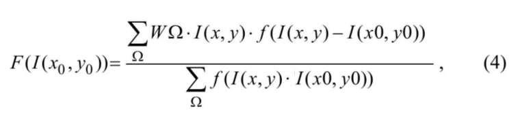
where Ω is the neighborhood of a pixel with coordinates (x0, y0), (x, y) ∈ Ω; WΩ is the two-dimensional LPF filter kernel; f is a function that reaches the maximum, if the difference of the brightnesses of the pixels in Ω and the pixel I(x0, y0) is minimal; the expression in the denominator is a normalization function.
Often WΩ and f are the Gaussian functions, and the neighborhood Ω has a diameter of five or more pixels [8]. The action of the bilateral filter is such, that if the image has the slight changes in the neighborhood of a pixel, then, it is smoothed out. And if there is a sharp transition of brightness, then it is not smoothed, because the corresponding samples of the kernel WΩ are multiplied by the value of the function f, which is close to zero for the sharp image details.
The bilateral filter (4) is hard in computations, especially if the HDR image is computed. In this work, the adaptive filter is proposed, which preserves the edges almost as well as the filter (4), but it is much simpler in the hardware implementation. Thanks to this, the processing of the HDR image is simplified and accelerated. Besides, the intermediate results of this filter can be effectively used for the recognition the patterns in the input image.
III. HDR adaptive filter
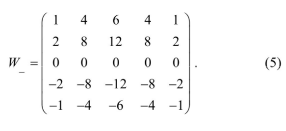
An adaptive filter is proposed, which preserves the edges of the image instead of the filter (2). The adaptive filter structure is shown in Fig. 2. Such a filter consists of an image analyzer and an adjustable two-dimensional LPF. The image analyzer uses the idea of the Harris-Laplace detector [9]. Its output signal is the eigenvector of the autocorrelation matrix of the neighborhood Ω. There are five detectors W|, W_, W/, W\, W*, which are sensitive to the vertical, horizontal, inclined edges, or points in the image, and one LPF WLPF, which estimates the local brightness of the image.

Fig.2. Adaptive filter structure
For example, the kernel for the horizontal line selection looks like the following:
The output of such a detector is the signal in the logarithmic scale. The analyzer decision unit selects the maximum detector signal and outputs it accompanying the detector number. The logarithm of the local brightness is subtracted from it to provide the normalized signal D(x,y) in the high dynamic range. Fig. 3 illustrates the results of the image analyzer for the image of the character ® with different scales, rotations, and illuminations. The color of a pixel in it means the detector number.
The adjustable LPF operates as follows. It contains a table ROMK of the filter kernels, which are distinguished depending on the local image type, i.e., if it is vertical, horizontal, inclined edge, and on its strength. Up to 40 different kernels are stored in this table. All of them are pre-normalized. Therefore, the filter does not need the complex dynamical normalization, which is used in the genuine bilateral filter (4).
The output signal of the image analyzer selects the proper kernel in the table for every pixel in the image. For example, a uniform field is filtered by the Gaussian filter kernel with the high blur. When the edge is detected, then the filter kernel is selected, which is sensitive to this edge. This kernel matrix has the nonzero coefficients, which form in the plane the tight ellipse. As a result, the image is filtered providing the sharpness of the objects. The resulting adaptive filter computes the illumination function F(I) and is substantially less complex than the bilateral filter (4).
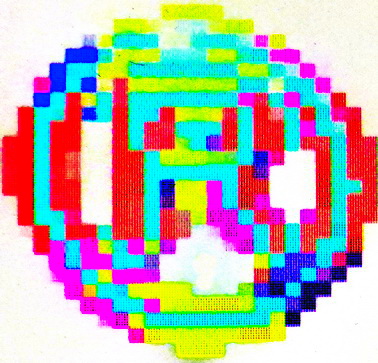
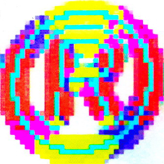

Fig.3. Results of the image analyzer
To search for the feature points in the image two additional computational steps are needed. First of them is the noise filtering. Because of the logarithmical scale of the image D(x,y), the usual linear filtering methods are not fitted. In this situation, the maximum homogeneity neighbor (MHN) filter is fitted well [11]. The MHN filter has a set of image stencils. Due to the genuine MHN filtering, the pixel D(x,y) is substituted by the average value of pixels which fall in some of the stencils if these pixels have the homogeneous brightness. Here, the filtering process is simplified because the pixels D(x,y) have the small bit width and are distinguished in five different colors, as in Fig. 3. Then, the pixel D(x,y) is smoothed if a stencil is found, which covers the pixels of the same color. Otherwise, this pixel gets the background color. Therefore, such a filter can be designed on the base of wide look-up tables.
In the second step, the feature points are found. These points are blobs, corners in the edges, corners in the lines, intersections of the lines and edges. These feature points are searched using the MHN method as well. But here a set of spatial stencils is used. Each of them is adapted to the considered feature, for example, to a corner, which has the proper angle and direction in the space. The stencil selects the pixels of the specific color in the neighborhood (see Fig. 3). If the color of this pixel and pixels in its locality is cyan, then it belongs to a blob. If the cyan pixel is surrounded by yellow pixels above and below, then it belongs to a horizontal line, and so on. The selected feature point has the coordinates (x,y) of the respective feature filter with the maximum output magnitude in the considered image locality.
Comparing to the Harris-Laplace detector [9] this feature point detection is much simpler when it is performed in FPGA. But it does not provide the scalable detection. To do the scalable feature point searching, the system has to be doubled many times for the initial frame and for its decimated copies.
IV. Experimental results
To process the image with the HDR compression, the video camera was designed on the base of the Lattice HDR-60 board, which utilizes ECP3-70 FPGA. As a video sensor, the Aptina MT9M024 chip was used, which produces the 720∙1280 HDR image stream at a rate 60 frames per second with a dynamic range of 120 dB.
For the image processing, the modules of image debayerization, median filtering, color conversion, brightness histogram former, and others were developed. Among them, the module of the real-time HDR compression plays the main role.
The colored image channel is split into the brightness and color channels. The brightness signal with the 20-bit pixels is compressed to 8-bit pixels due to the equations (1)-(3). Then, the colored image is restored using the color channel. By this process, the color signal is compressed using the square root function.
The image analyzer filters have the kernels like (5). Therefore, they are implemented as the pipelined multiplier-free adder networks. For example, to implement the filter with the kernel (5) a tree network of 20 adders is designed, which has four pipeline stages. These networks provide both high-speed computations for the multi-bit data and small hardware volume comparing to the network of the hardware multipliers. The functions Γ(y) (2) and β(y) (3), which perform the compression of the dynamic range, and the contrast increase, are implemented using the piecewise linear interpolation.
The pipelined datapaths of the different signal processing steps of this system are designed using the method of the spatial synchronous data flow graph (SDF) mapping. This method consists in representing of an algorithm iteration by SDF, placing it in the multidimensional space using a set of rules and describing it in VHDL language [12]. The method provides the design of pipelined datapaths for FPGA providing the maximum ratio of the throughput to the hardware volume.
The configured project of the system can operate with the clock or pixel frequencies up to 130 MHz. The hardware costs of the system, which is configured in FPGA, is shown in Table 1. This table analysis shows that the system occupies only a quarter of the whole FPGA resources, and there is a room for the development of an additional system for the simple pattern recognition.
TABLE I. Hardware costs of the HDR compressor
| FPGA hardware | Configured | Available | % |
| CLB slices | 8563 | 33264 | 25,7 |
| Registers | 5694 | 66528 | 8,6 |
| Multipliers 18х18 | 34 | 128 | 26,6 |
| BlockRAMs 1024х18 | 56 | 240 | 23,3 |
Comparing to the analogous systems [4,5], this system provides the much complex computations and more effective HDR image processing supporting the real-time operation and using the middle volume FPGA.
Fig.4 illustrates the use of the developed video camera by the computing the blood image from the LCD display. The image was taken from the repository of the information on the biochemicals and cells in blood and body fluids [13].
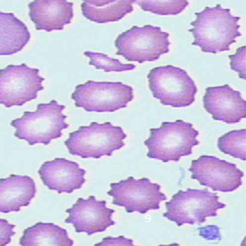
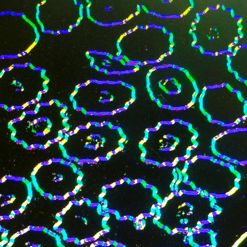
Fig. 4 Initial image and results of its processing by the analyzer
Fig. 4 analysis shows that the video camera can reliably select the cells and represent its features, which helps to recognize and make classification of the unnormal cells. Such cells have a set of feature points representing the angles which form a ring.
V. Conclusion
The modification of the HDR image compression algorithm based on the Retinex method is proposed. It consists in the replacing of the bilateral filter, which calculates the image illumination, to an adaptive filter, which preserves the image edges.
The filter is based on a set of the feature detectors and the Gaussian filter. Such a filter greatly reduces the compression complexity and enables the processing of the video signal in real time. A prototype of the HDR video camera is designed which provides the sharp images both in illuminated and in darkened areas of the scene. It can be effectively used as a camera of the high-resolution video surveillance system. Moreover, the resulting signal detector of this camera can simplify the design of the pattern recognition system. The next step will be the design of the medical pattern recognition system which operates in the strong brightness conditions.
References
[1] R. M. Rangayyan, “Biomedical Image Analysis”, CRC Press, 2005.
[2] D. J. Neal1 and S. Rahman, “Video surveillance in the cloud?”, International Journal on Cryptography and Information Security (IJCIS),vol.2, No.3, 2012.
[3] M. Birem, F. Berry, “DreamCam: A modular FPGA-based smart camera architecture”, Journal of Systems Architecture, vol. 60, 2014, pp. 519 –527.
[4] T. Ai, M. A. Ali, G. Steffan, K. Ovtcharov, S. Zulfiqar, and S. Mann, “Real-time HDR video imaging on FPGA with compressed comparametric lookup tables”, 27th IEEE Canadian Conference on Electrical and Computer Engineering (CCECCE), 4-7 May, 2014.
[5] P.-J. Lapray, B. Heyrman, D. Ginhac, “HDR-ARtiSt: An adaptive real-time sSmart camera for high dynamic range imaging”, Journal of Real-Time Image Processing, Springer Verlag, 2014, pp.1-16.
[6] J. J. McCann, E. H. Land, “Lightness and retinex theory”, Journal of the Optical Society of America, vol. 61, No. 1, 1971, pp. 1 – 11.
[7] S. Saponara, L. Fanucci, S. Marsi, G. Ramponi, D. Kammler, E. M. Witte, “Application-specific instruction-set processor for Retinex-like image and video processing”, IEEE Trans. On CAS, II: Express Briefs, vol.54, No.7, 2007, pp. 596 – 600.
[8] S. Paris, P. Kornprobst, J. Tumblin, F. Durand, “Bilateral filtering: theory and applications”, in: Foundations and Trends in Computer Graphics and Vision, vol. 4, No. 1, 2008, pp. 1–73.
[9] M. Hassaballah, A. A. Abdelmgeid, H. A. Alshazly, “Image features detection, description and matching”, in: Image Feature Detectors and Descriptors. Foundations and Applications. A. I. Awad, M. Hassaballah, Eds. Springer, 2016, pp. 11- 46.
[10] C. Schmid, G, Dorko, S, Lazebnik, K. Mikolajczyk, J. Ponce, “Pattern recognition with local invariant features’, in: Handbook of Pattern Recognition and Computer Vision, 3rd ed. C. H. Chen, P. S. P. Wang, Eds. World Scientific Pub. 2005, pp. 71 – 92.
[11] M. Nagao, and T. Matsuyama, “Edge preserving smoothing”, Computer Graphics and Image Processing, vol. 9, No. 4, 1979, pp. 394–407.
[12] A. Sergiyenko, A. Serhienko, A. Simonenko “A method for synchronous dataflow retiming”, IEEE First Ukraine Conference on Electrical and Computer Engineering (UKRCON), May 29 – June 2, 2017, pp. 1015-1018.
[13] Medical Laboratories Portal. http://www.medical-labs.net/wp-content/uploads/2014/01/Crenated-Cells.jpg