A Method for Mapping Unimodular Loops into Application Specific Parallel Structures
(Published in 2nd Int. Conf. “Parallel Processing and Applied Mathematics”, PPAM’97, Zakopane (Poland), Sept.2-5, 1997, p362-371)
A METHOD FOR MAPPING UNIMODULAR LOOPS INTO APPLICANION SPECIFIC SIGNAL PROCESSORS
A.M. Sergyienko*, Guzinski A.**, Kaniewski J.S.**
*Department of Computer Science, National Technical University of Ukraine, KPI-2020, Pr. Pobedy, 37, 252056, Kiev, Ukraine, E-mail: kanevski@comsys.kpi.ua
**Institute of Math.& Computer Science, Technical University of Coszalin, Coszalin, Poland, E-mail: kanievsk@tu.koszalin.pl
ABSTRACT
A method for mapping unimodular loop nests into application specific structures is presented. The method consists in representing the reduced dependence draph of the algorithm in multidimensional index space and in mapping this graph into processor subspace and event subspace. Some restrictions, which constrain the reduced dependence draph, help to simplify the mapping process, and to get pipelined processing units. An example of IIR- filter structure systhesis illustrates the mapping process.
Keywords: algorithm mapping, application specific circuits, digital signal processing.
1. Introduction
The automatic development of ASICs for digital signal processing (DSP) helps to reduce both the way from the idea to the market and development costs. The silicon compiler can ensure the direct way from some DSP algorithms to the chip which computes this algorithm. And the design period is defined first of all by the technological constraints [1]. The use of programmable devices, such Field Programmable Gate Arrays (FPGAs), can provide hardware prototypes with minimum fabrication delay [2].
Such steps of the design process as testing of signal processing algorithm, logic design and verification, routing and translation the circuit into the format of the program for FPGA are automatized now. But the development of the structure which realizes the given signal processing algorithm is implemented an hand and for this job skilled specialists are needed [2]. Therefore the development of programming tools for mapping the DSP-algorithms into structures which adapted to the properties of FPGAs is of great importance.
DSP algoritms usually process a data flow in real time and therefore have an iterative nature. We will consider DSP algoritms which are represented with the unimodular loop nests or regular recurrent equations. The kernel of the loop nest has one or more statements, such as:
Sti: a[I] = f(a[I–D1], b[I–D2],…),
where I is the index vector of variables which represent a point in the iterational space, Dj – vector of increments to the index of j-th variable which characterizes data dependence between iterations (I–Dj) and I.
This means that all computations which belong to a single iteration can be sheduled in such a way, that they begin in a single moment of time [5]. There are well known methods of mapping such algorithms into systolic array structures (see, for example, [3…8]). These methods are based on affine transform of the iterational space Zn, I ∈ Zn with the matrix P, into subspase Zm of structures and subspace Zn-m of events. As a result of the transform, the statement Sti of the iteration I is processed in the processing unit (PU) with coordinates KS = PS I in the time step which is signed as KT = PT I, where KS ∈ Zn, KS ∈ Zn-m, and P=(PST, PTT)T.
If the algorithm has cycles of dependencies between iterations, that is expressed by cyclic reduced dependence graph, then mapping such algorithm is more complex [5]. The methods for mapping these algoritms are known which are based on mapping each statement Sti using the separate affine mapping function [8, 9]. Then the searching for algorithm mapping is implemented by optimizing the inequality system which express restrictions to the affine mapping functions. The solving this problem can give the optimum solution, but this solving is rather hard [9].
Mehtioned above methods have a set of restrictions which do not permit its direct using for the development of DSP structures. First of all, it is considered that the asignments Sti which belong to a singe iteration must to be processed simultaneously during a single time step. Therefore, although the systolic array represent a multidimensional pipelined computer system, separate and complex operators and statements cannot be computed in pipelined manner. The second restriction is that the mapping result represent a structure not with the given throughput, but with the maximum thronghput. This restriction is something reduced by the synthesis of fixed size systolic arrays but the problem of single time step processing of complex operators takes a place [8, 10, 11].
The use of the pipelined PUs offers the increased throughput of DSP-processor due to the possibility to begin the next operator processing before completing the previons one. Therefore, the development of pipelined PUs is attractive for hardware relization of any algorithms, among them DSP-algoriths. In [12] a method for systolic array design with pipelined PUs is proposed. But this method is not suitable because it consists in the manual introduction of pipeline stages into the given systolic array structure.
This work deals with a new method for designing application specific DSP-processor structures by mapping algoritms which are given as unimodular loops.
2. Assumed algorithms and goals of the method.
The proposed method represent modified known methods for structured synthesis of systolic arrays. There are the following goals of the method modifications:
- processing onerafors for more than a sigle cycle of time. This provides designing DSPprocessors with given throughput, computing complex operators of the algorithm, and operators can have different complexity. The cyclic dependencies in algorithm are approved too. Different statemet Sti of the loop kernel can start their processing at different clock cycles, and this enlarges the area of processed algorithms;
- internal pipelining of PUs. By pipelining the PUsinternally, the latency of PU can become more then one cycle of time. But the PU has higher throughput because the maximal allowable clock frequency is higher;
- hardware sharing, that means that the same hardware unit exelutes similar statements in sequential order, unlike one executes a single statement when known methods are used.
Consider the algorithm which is represented with a single loop:
for i = 1, Ui do
 (y1(i),...,yp(i)) = f(x1(i+di1),...,yq(i+diq))
 end.
(1)
Here the operator f is processed by the algorithm which consists of Uj unar and binar statemens Stj , there are not any conditional ststements. Therefore the algorithm can be represented as the following:
for i = 1,Ui do
 {statement St1}
 . . .
 Stj: y[i,j]=ϕj,k(y[i-di1,j],y[i-di2,j])
 . . .
 {statement Stuj}
 end,
(2)
where ϕj,k(x,y) is the operator of the k-th type which processed the operands x and y. This loop can be transferred into the three-staged loop nest. In the (i, j, k)-th iteration of such a loop nest only j-th statement of k-th type is processed or nothing is done:
for i = 1,Ui do
 for j = 1,Uj do
   for k = 1,Uk do
   if (j,k)∈Φ then y[i,j]=ϕj,i(y[i-di1,j],y[i-di2,j])
   end
 end
end,
(3)
where Φ is a set of feasible couples (j,k), which specify type and order of operator implementation in the algorithm (2).
Therefore, the loop (2) which kernel consists of several different statements can be represented as a triple loop nest (3). The computing of this loop nest takes place in the three dimensional iterational space K3 = { 1 ≤ i ≤ Ui, 1 ≤ j ≤ Uj, 1 ≤ k ≤ Uk}⊂ Z3. Each operator is represented by the vector Ki ∈ K3, and the dependence between two operators Ki, Kl is represented by the vector of dependence Dj = Kl – Ki. In most cases the vector Dj represent a variable which is a result of the operator Ki, and is transferred to different operators Kl as a imput variable. A generalised loop nest with such a kerrel can be represented in such a manner too.
Alove mentioned methods of the application specific structure synthesis suppose that PUs implement a given set of operators. In this paper application specific PUs are considered, which implement a single operator ϕk. A set of PUs for the DSP applications can constist of simple PUs like adder, multiplier, ROM, and their storage unit can be FIFO, which can consist in most cases of a single register of the result.
3. Mapping unimodular cycles into the application specific processor structure.
In the methods, described in [3,…,8, 10-12] the graph GA of the algorithm is represented in the n-dimensional index space Zn. The graph GA of the systolic algorithm is a regular lattice, therefore it is represented by its compact form, which consists of unrgual dependence vectors Dj, and processing domain Kn ⊂ Zn. When the algorithm has a complex loop kernel, like in the algorithm (2), then a reduced dependence graph GAR can represent the compact form of the one. This oriented, in common case, cyclic graph has N nodes of operators Ki and M edges of dependencies Dj.
Consider a simple example of an algorithm:
 for i = 1, N do
     for 2 j = 1, M do
     St1: a[i,j] = b[i-1,j-1];
     St2: b[i,j] = a[i,j];
     end
 end
This algorithm is represented by reduced dependence graph GAR which is shown on the fig. 1.

Vectors-nodes D1 and D2 represent movings of dates a and b between statements St1, St2, and are weighted with the distance vectors (0, 0)T and (1 1)T respectively.
The reduced dependence graph GAR can be represented in the n-dimensional space by the matrix D of data dependence vectors Dj, matrix K of vectors-nodes Ki, and incidence matrix A of this graph. Then matrices K, D, A form an algorithm conficuration CA.
The following definitions and depedencies are true for configurations CA . The configuration CA is correct if Ki ≠Kj; i, j = 1,…,N, i ≠ j, i.e. if there is a linear depedence between configuration matrices, i.e.
D = KA; K = D0A0-1, (4)
where A0 is the incidence matrix for the maximum spanning tree of GAR , and D0 is a matrix of vectors-arcs of this tree. For example, for the graph on the fig.1 the following equation takes place:

where DB is a basis vector-edge, which connect the zero point of the space with the vectornode K1.
The sum of vector-edges Dj, which belong to any loop of the graph GAR must be equal to zero, i.e. for the i-th loop the following equation is true

where bij is the element of the i-th row of the cyclomatic matrice for the graph GAR. Configurations CA1 = (K1,D1,A1) and CA2 = (K2,D2,A2) are equivalent if they are correct and represent the same algorithm graph, i.e. A1 = A2.
The following theorem is used to implement the equivalent transformations of configurations.
The correct configuration CA1 is equivalent to the configuration CA2 iff A1= A2 and K2= F(K1), where F is an injective function. For example, the following transformations give equivalent configurations: permutations of vectors Ki in the space Zn or permutations of columns of the matrix K1, multiplications of the matrix K1 and non-singular matrices P.
The graph GS of the processor structure is represented by its configuration GAS = (KS, DS, A), where KS is the matrix of vectors-nodes KSi ∈ Zm which give coordinates of PUs, and DS is the matrix of vector-arcs DSj ∈ Zm which represent connections between PUs, m < n.
Finally, a precedence configuration CT = (KT, DT, A) consists of the matrix KT of vectors KTi ∈ Zn-m, matrix DT of vectors DTj and matrix A. Here vectors KTi represent time slots of executing operators of the algorithm. In a correct configuration CT a vector-edge DTj = KTl KTi means that the operator of the node KTi must precede in time to the operator of KTl. The scedule function R(KTi) = ti implements the mapping of the space Zn-m of events onto the time axis, and determines the actual time associated with an operator.
The configuration CT is correct, or , in other words, the precedence condition is true, if for any couple of vectors-nodes KTi and KTl the inequality R(KTl) ≥ R(KTi), is fulfilled, where KTi precede to KTl.
One can prove that if the schedule R is a linear and monotone function, then the configuration CT is correct iff
DTj ≥ 0 (6)
where DTj is the unweighted dependence vector of the reduced dependence graph GAR, j = 1,…,M.
The function R(DTj) gives the delay between the moment of computing the j-th variable and the moment when this variable is fed into another PU. This delay determines the upper bound for the volume of RAM where this variable is stored.
Consider the method for searching of space and time components for the algorithm (2). This algorithm is mapped into application specific processor structure which processes its kernel with the period of τ time clocks. This method can be generalized for the mapping of multinested loops, for example, using hierarchical approach [13].
As mentioned above, the algorithm (2) can be represented in the three dimensional index space, in which vectors-edges Kl have coordinates (j, k, i)T, where i equals the iteration number, j equals the statement number, and k equals the type of the statement operator. In such a manner one can add a forth dimension which represents the number q of the time slot in the given iteration. This algorithm is represented by the reduced dependence graph GAR and respectively, by the algorithm configuration CA. The coding of the weight of the vector-edge Dj is implemented in such a way. Value i<0 of the iteration number and zeroed value of the time slot mean that the respective edge Dj has the weight which is equal to i.
The algorithm configuration CA is equal to the composition of structure configuration CS and configuration of events CT , namely
and if Kl = (j, k, i, q)T, then KSl = (j, k)T , and KTl = (i, q)T.
At the first stage of the synthesis the searching for the space component of the mapping is implemented, namely searching for matrices KS and DS. In the vector KSl = (j,k)T, the coordinate j equals the number of PU, where the l -th operator is processed, and k equals the type of it.
The forming of the matrix KS is a combinatorial task. This task consists in distributing Mk operators of the k-th type among ]Mk/τ[ processing units of the k-th type. As a result, MS groups of equal columns are formed in matrix KS , and the number of columns in each of them is less or equal to τ , where MS is the number of PUs in the resulting structure. The maximum hardware utilization effectiveness of the j-th PU is achieved if the number of columns with j-th element in the first row of the matrix KS is equal to τ. Then the matrix DS is computed by the equation : DS = KS A.
On the second stage the time component of the mapping is searched in the form of the matrices KT and DT . These matrices must satisfy the conditions of algorithm configuration correctness, correctness of the configuration of events, and identity to zero of summs of vectors-nodes which belong to cycles of the graph GAR. Besides, one can to prove that the given algorithm will be processed correctly iff
∀KTl ∈ KT(KTl = (i, q)T, i > 0, q ∈ (0, 1,…,τ-1)).
The strategies of the searching for space and time components of the mapping can be investigated by considering the next example of the synthesis of the application specific processor structure.
4. Example of the synthesis of the IIR-filter structure.
Consider an example of the structural synthesis of the recursive filter which computes the following equation:
y[i] = x[i]+ay[i-2]+by[i-1].
This equation is computed by the algorithm which is given by the following uniform loop:
 for i = 1, N do
     St1: y1[i] = a*y[i-2];
     St2: y2[i] = b*y[i-1];
     St3: y3[i] = x[i]+y1[i];
     St4: y[i] = y2[i]+y3[i];
 end.
The fig.2 illustrates the reduced dependence graph of this algorithm.
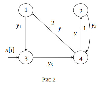
Each of the statements St1,…,St4 must be computed no less than a single time slot. The weighted edges which begin in the third and fourth node express the delay of the variable y[i] for one and two iterations, and cannot express the delay of the computing the statement St4. Therefore, in these edges intermediate nodes must be added. The fig.3 illustrates the modified reduced dependence graph of the algorithm.
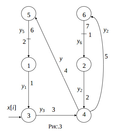
The modified reduced dependence graph represent the following algorithm.
 for i = 1, N do
     St1: y1[i] = a*y5[i-2];
     St2: y2[i] = b*y6[i-1];
     St3: y3[i] = x[i]+y1[i];
     St4: y[i] = y2[i]+y3[1];
     St5: y5[i] = y[i-2];
     St6: y6[i] = y[i];
 end.
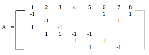
It is useful to select the algorithm processing period be equal to τ = 2, because the algorithm has two addition operators and two multiplication operators, which can be processed on a single adder and single multiplier. The reduced dependence graph has the following incidence matrix:
The spatial component of the algorithm mapping is searched as the matrices KS and DS. The acceptable coordinate values of the vectors-nodes Kti are placed in the matrix KS: KS =((1,1)Т (1,1)Т (2,2)Т (2,2)Т (3,0)Т(3,0)Т )
Here the coordinate k = 0, 1, 2 represents operators of identity, addition, multiply, respectively, and equal coordinates j mean that respective operators will be computed in the same PU. The matrix DS of relative interprocessor connection coordinates is derived from the equation:

Then the timing component of the algorithm mapping is searched. First of all the known vectors are derived, which are weighted dependence vectors-edges: DT6 =(-2,0)T and DT7 =(-1,0)T
The timing function R = (τ 1) = (2 1) is derived on the base of the algorithm processing period τ = 2. For the purpose of minimizing the register number in the local memory of adder and multiplier Pus, the vectors-edges DTj, which beginning conform to nodes 1,…,4, must be derived from the equation R*DTj = 1 or 2, i.e. must be equal to (0 1)Т, (1 -1)Т,or (1 0)Т. This condition satisfies the monotonity of the algorithm mapping.
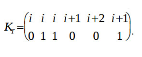
To satisfy the injectivity condition, the coordinates q of the vectors Ktl with the equal coordinates j must be unequal. For example, the vector KT1 is equal to (X 0)Т or (X 1)Т, and KT1 is equal to (X 1)Т or (X 0)Т, where X is the previously unknown value. The respective coordinates q of the relative delay vectors DTl are derived from the equation DT = KT A. Besides, these relative delay vectors DTl must satisfy the condition of identity to zero of summs of vectors-nodes which belong to cycles of the graph GAR:
DT1+DT3+DT4+DT6 = 0 ;
DT2+DT5+DT4+DT6 = 0.
These conditions are satisfied by the only solution:
The designing results are the reduced dependence graph GAR, which is represented in the four dimensional space, the structure graph GS, the derived structure of the IIR filter, and algorithm graph GA which are illustrated by the fig.4.
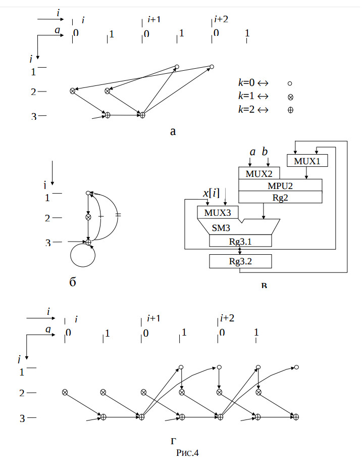
Fig.4. The reduced dependence graph a); the structure graph b); the derived structure of the IIR filter c), and algorithm graph d).
The features of this structure are maximum hardware utilisation effectiveness of its adder and multiplier, and its operating in pipelined regime, the minimum period of time slot, which is equal to the multiplier delay.
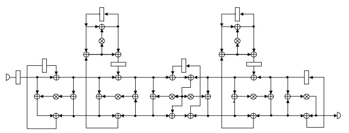
The 5-th order elliptical filter was chosen as the more complex testbench example [1]. It was compared to the results of such known software tools like SPAID and HAL [14], which are shown in the following table. The data flow graph of this filter is illustrated by the fig.5. It is considered that in the resulting structure the multiplication lasts 2 clock cycles and the addition lasts 1 clock cycle. Two structure sets were considered. The regular multipliers were used in the first one, and pipelined multipliers were used in the second one.
| Parlab | SPAID | HAL | |||||||
| Regu- lar |
Pipelined | Regu- lar |
Pipelined | Regu- lar |
Pipelined | ||||
| Multi- pliers |
2 | 1 | 1 | 3 | 2 | 2 | 3 | 2 | 1 |
| Adders | 3 | 3 | 2 | 3 | 3 | 2 | 3 | 3 | 2 |
| Multi- plexor inputs |
55 | 41 | 43 | 37 | 35 | 24 | 36 | 37 | 28 |
| Regis- ters |
11 | 11 | 10 | 21 | 21 | 21 | 12 | 12 | 12 |
| Compu- tation period τ |
17 | 17 | 19 | 17 | 17 | 19 | 17 | 17 | 19 |
The resulting structures have minimum hardware volume due to the register account, and , what is very important, to the multiplier account. The negative effect consists in the increased multiplexor input number comparing to the SPAID and HAL results.
5. Conclusion.
In this work the new method for mapping the algorithms which are represented by unimodular loops is presented. This method is developed as the evolution of methods of algorithm mapping which are publisched in [13, 14, 15]. The method is intended for the synthesis of application specific processor structures which operate in the pipelined regime with high load balancing. The given method is realized in the framework Parlab which operates on the IBM-PC platform in the Windows environment. This framework helps to develop application specific processors for DSP and other applications. The results of this development can be utilized by programming the modern FPGAs.
References
1. Rabaey J., Vanhoof J., Goossens G., Catthoov F., DeMan H. CATHEDRAL-II: Computer Aided Systhesis of Digital Signal Processing Systems. IEEE Custom Integrated Circuits Conference, 1987, p. 157-160.
2. Isoaho J., Pasanen J., Vainio O. DSP Sytem Integration and Prototyping With FPGAs. J. of VLSI Signal Processing. V 6, 1993, p. 155-172.
3. Rajopadhye S.V., Synthesizing systolic arrays with control signals from recurrence equations. Distributed Computing. V3, 1989, p. 88-105.
4. Fortes J., Moldovan D. Data broadcasting in linearly scheduled array processors. Proc. 11 th Annual Symp. on Comp. Arch., 1984, p. 224-231.
5. Rao S.K., Kailath T., Regular iterative algorithms and their implementation on processor arrays. Proc of IEEE, V. 76, 1988, N 3, p. 259-270.
6. Moldovan D.I. On the design of algoritms for VLSI Systolic arrays. Proc. IEEE, V. 71, 1983, N 1, p. 131-120.
7. Kung S.Y. VLSI Array Processors, Eigenwood Cliffs, N.J.: Prentice Hall, 1988.
8. Quinton P. and Robert Y. Systolic algorotms and architectures. Prentice Hall and Masson, 1989.
9. Darte A., Robert Y. Mapping uniform loop nests onto distributed memory architectures. Parallel Computing, V. 20, 1994, p. 679-710.
10. Moldovan, D.J. Partitioning and mapping algorithms into fixed size systolic arrays. IEEE Trans. Computers, V35, N1,1986, p.1-12.
11. Wyrzykowski R. and Kanevski J.S. Systolic-type implementation of matrix computations. Proc. 6-th Int. Workschop on Parallel Processing by Cellurar Automata and Arrays, PARCELLA’94, Potsdam (Germany). p. 267-272.
12. Valero-Garcia M., Navarro J.J., Llaberia J.M., Valero M. and Lang T. A method for implementation of one- dimensional systolic algorithms with data contraflow using pipelined functional units. J. of VLSI Signal Processing, V. 4, 7-25, 1992, p. 7-25.
13. Kanevski, J.S., Sergyienko, A.M., Piech H. A method for the structural synthesis of pipelined array processors. 1-st Int. Conf. “Parallel Processing and Applied Mathematics”, PPAM’94. Czestochowa (Poland), Sept. 14-16, 1994, p. 100-109.
14. Kanevski, J.S., Sergyienko, A.M. Mapping mumerical algorithms into multipipelined processors. Proc. Int. Workshop “Parallel Numerics’94”, Smolenice (Slovakia), 1994, p.192-202.
15. Kanevski, J.S., Loginova L.M. and Sergyienko, A.M. Structured design of recursive digital filters. Engineering Simulation. OPA, Amsterdam B.V., V13, 1996, p.381-390.