Testbench for the filter testing
A.Sergyienko
National Technical University of Ukraine “KPI”,
Email: aser@comsys.kpi.ua
To test the filter, some special signals are inputted in it and the filter reaction is investigated. The sine waves are usually selected as such input signals because they do not exchange their form but only their magnitude. This is explained by the fact that the sine wave is the eigenfunction for the linear filters. To say more precisely, the genuine eigenfunction is the analytical (complex) signal, which is represented by the couple of cosine (inphase) and sine (quadrature) signals.
A set of reactions to the analytical signal with different frequencies is named as the frequency characteristic of the given filter. The magnitude-frequency characteristic and phase-frequency characteristic are usually distinguished for the filter. It is recommended to test the DSP filters by deriving these characteristics.
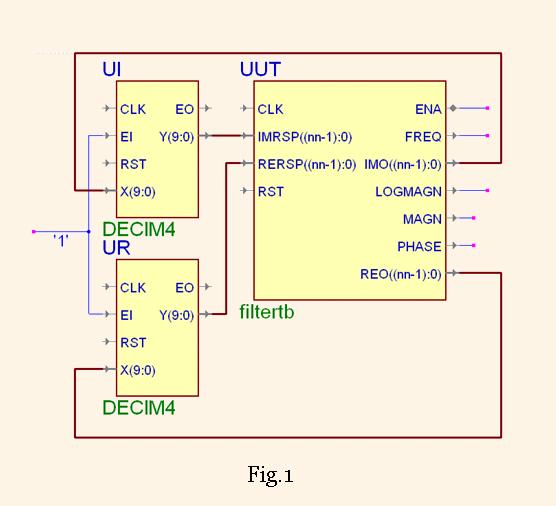
For this purposes the filter testbench component is proposed for the use in the digital filter design and investigations of them. The connection of the filter component to the tested filter instantiations (UI, UR) is shown in Fig.1. Note that two copies of the same filter must be attached to the FilterTB component.
The component named FilterTB has the following entity declaration
      entity FilterTB is
      	generic(fsampl:integer := 1000;
      		fstrt: integer:=0;
      		deltaf:integer:=20;
      		maxdelay:integer:=100;
      		slowdown:integer:=3;
      		magnitude:real:=1000.0;
      		nn:natural:=16);  ---bit width

      	port(CLK : in STD_LOGIC;
      		RST : in STD_LOGIC;
      		RERSP : in STD_LOGIC_VECTOR(nn-1 downto 0);
      		IMRSP : in STD_LOGIC_VECTOR(nn-1 downto 0);
      		REO : out STD_LOGIC_VECTOR(nn-1 downto 0);
      		IMO : out STD_LOGIC_VECTOR(nn-1 downto 0);
      		FREQ : out INTEGER;
      		MAGN:out INTEGER;
      		LOGMAGN:out REAL;
      		PHASE: out REAL ;
      		ENA: inout STD_LOGIC);
      end FilterTB;
The generic and port meanings are shown in the following table
| fsampl | Integer sampling frequency, for example, 1000 kHz |
| fstrt | Starting frequency fo, the first frequency which is analyzed |
| deltaf | Frequency increase d, so in k steps the generator will output the frequency fo + k*d |
| maxdelay | The delay in signal samples, after which the output signal parameters will be estimated. Usually it is slightly higher than the maximum (group) delay of the filter which is tested. |
| slowdown | Factor, in which the filter speed is slowed down. If the input samples enter each clock cycle then slowdown=1, if the samples go in odd clock cycles then slowdown=2, etc. |
| nn | Input and output data width |
| magnitude | Integer magnitude of the generated sine/cosine waves. For example, if nn=8 then magnitude is any positive number less than 127. |
| REO,IMO | Cosine/ sine waves, represented by the nn bit integers, outputted by the component |
| RERSP,IMRSP | Filter output signals , which are responses to the cosine/ sine waves, and which must be ported to the nn-bit width inputs |
| FREQ | Frequency code of the given sine/cosine waves in this but the previous frequency step, which is equal to fo + (k-1)*d |
| MAGN | Estimated magnitude of the signal RERSP,IMRSP at the frequency FREQ |
| LOGMAGN | Estimated magnitude of the signal RERSP,IMRSP at the frequency FREQ in the logarithmical scale, i.e. in decibels. Note, the signal with the given magnitude is 0 db |
| PHASE | Estimated phase of the signal RERSP,IMRSP at the frequency FREQ represented in the range ± π |
| ENA | Enable signal, which strobes the filter inputs when slowdown>1 |
The magnitude-frequency characteristics, which are measured by this testbench for the 2-stage CIC filters DECIM4 are shown in the Fig. 2.
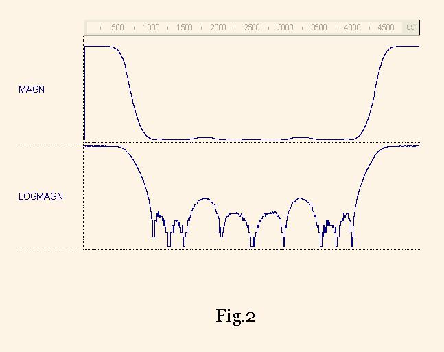
The Fig2 shows that the measured suppression level is higher than 30 db, the low pass band width is equal to 0.1 fs (at the level of -3 db), the intermediate band width is equal to 0.08 fs . The frequency value is sampled in the waveform FREQ .
To prevent the I/O data type conversions, three variants of the testbench entities are present for the real, integer and STD_LOGIC_VECTOR data types respectively.