FIR filter soft core generator
Represented in RUC’01, Szczecin, Poland
Anatoli Sergyienko,Vladislav Vasylienko
National Technical University of Ukraine “KPI”, Kiev, Ukraine, Email: aser@comsys.kpi.ua
Oleg Maslennikov,
Technical University of Koszalin, Poland, Email: oleg@moskit.ie.tu.koszalin.pl
Abstract
A new FIR filter soft core generator is represented which utilizes structural properties of FPGA, minimizes its hardware volume. It provides the design of highly pipelined structures with extremally high clock frequency which are described on VHDL.
1. INTRODUCTION
The modern system on the chip (SOC) technology is based on a set of principles, one of them is the core generator use. Due to its flexibility, reusability the core generator can substitute the very large library of cores of a single type. Tunable core generators help to optimize the speed, hardware, and energy consumption of the resulting project.
Finite impulse responce (FIR) filters are widely used in digital signal processing systems due to their high throughput, easy procedures of their characteristic calculation, phase characteristic linearity. The implementation FIR filters in FPGA has a set of advantages, like high throughput, hardware utilization effectiveness, and any rate of calculating precision because of full adaptation of implemented structure to the filtering algorithm. In many special applications, like high speed communications, FPGA is the only solution for FIR filter implementation.
The FIR filter core generators can support the development of high speed FIR filters with given filter length, impulse characteristic, signal-to-noise ratio. The Xilinx FIR core generator is well known due to high speed, small hardware volume of generated filters [1]. This generator generates so called firm cores, which are represented by the netlist. This is the source of such serious disadvantages like small range of parameter representation, and that this generator is tied to the small set of FPGA chip families. Due to the high measurements of generated relatively placed macros these filters are stiff and fit only large devices, and therefore they have inproper device area utilization.
In this paper the another FIR filter core generator is represented which generates filter cores described on VHDL, with increased throughput, minimized hardware, wide range of filter length, data and coefficient length, and which are implemented in the large set of FPGA families.
2. METHODS OF COEFFICIENT MULTIPLICATION IN FPGAS
FIR filter computation, or convolution consists in deriving the following sum of products
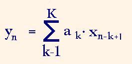
where xn-k+1 is the input data sample, ak is the filter impulse response coefficient, K is the impulse response length, yn is the output result sample with index n. To derive one resulting sample the filter has to implement averagely K multiplications and additions. Therefore the convolution is rather computation intensive.
Initially FPGAs were not intended for computation intensive applications like convolution. Therefore the multiplication units were firstly programmed as a set of logic equations or as a set of AND gates with an adder tree. When the application of FPGA in the intensive signal processing became clear and widely propagated, in the new FPGA families some elements were added which support the high speed multiplications. For example in Xilinx Virtex™ configurable logic blocks (CLB) the additional AND gates were added which support the multiplication, and then in VirtexII™ devices the separate multiply units were introduced.
In the most applications the convolution procedure has the multiplication to the constant coefficients. And the use of combinatorial circuits of multipliers for such a multiplication is rather abundance. Besides, the number of multiply units in the new FPGA families is not enough for many DSP applications. Therefore a set of techniques were proposed to utilize the property of constant coefficient multipliers (KCM). For example, taking into account that the average number of one bits in the m bit constant coefficient is equal to m/2 the KCM can be designed which consists of a tree of m/2-1 adders.
A.Peled and B.Liu have invented in1974 the method of deriving the sum of products named the distributed arithmetic. The method consists in the storing of up to 2K combinations of sums of K coefficients in the ROM. If the i-th bit silice of the input data set is inputted to the address input of this ROM then the read data is the sum of proper partial products. The whole sum of products is derived when up to m such sums of partial products are added in the result accumulator with the proper bit shift.
This method was proposed by L.Mintzer as the effective method to derive the sum of products in FPGAs [3]. It utilizes the property of 4 input look-up table (LUT) to be programmed as a high speed 16 bit ROM. This method is widely used in many DSP applications, and in the Xilinx FIR core generator as well [4]. To achieve the high throughput all the sums of partial products to the i Цth digits of multiplicants are calculated in parallel. Therefore such filters are called parallel distributed arithmetic (PDA) FIR filters. The disadvantage of the method consists in the extremally large ROM volume when the coefficient number K is larger than 8,Е,12, and more. To minimize this disadvantage the filter is divided to a set of blocks, each of them calculates the sum of K=4 or 5 of products.
Another way to get the multiplication to the constant coefficient was proposed in [5]. This method was shown in [6] as the effective multiply method for FPGAs. It based on the ROM which stores in its i-th location the coefficient a multiplied by i. Therefore the ROM of volume 2m represents the KCM to m bit dates. Such multiplier and the filter based on it are called ROM based multiplier (RBM) and RBM filter, respectively. When the ROM volume is too small then the input data is divided to l slices of p bits so as m ≤ lp, and the result is equal to the sum of l partial products. In [5] was shown that such multipliers for ASIC implementation are effective ones comparing to the usual 16×16 bit multipliers when the amount of the ROM volume is less than ca. 4 kbytes, and therefore the optimum slice width is p=4. The example of such KCM for 16 bit input data and 16 bit coefficients for 16 bit precision product and p=4 is illustrated by the fig.1. Such implementation of KCM has the following advantages.
* High throughput. The multiplier netlist has much of pipelined stages, and the logical paths are rather short. Therefore the minimum clock period can be extremally short and is equal to the delay in a single adder.
* Small hardware volume. The resulting hardware volume of RBM FIR filters is equal or less than hardware volume of PDA filters. It is less according to the following feature. Consider the coefficient a has a sequence of j equal (zero or one) bits. Then in the ROM the j-p+1 bit wide slice will have bits which are equal to each other. On the netlist synthesis stage such a bit slice will be minimized to the constant source. The FIR filters, which are used in the applications, usually have more than 70% of coefficients, which have more than 4 equal most significant bits, and more than 40% of coefficients having more than 7 such bits. Therefore when the RBM FIR filter is described on the language like VHDL, then the synthesized filter has in 1.1,…,1.6 times less hardware volume than the PDA filter has, depending on the filter coefficient set.
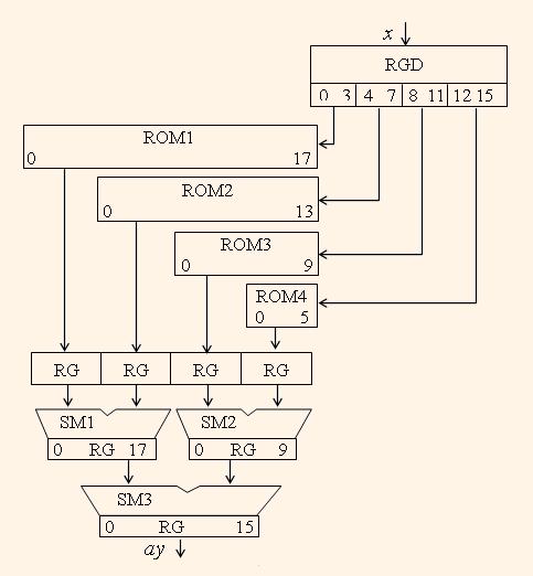
* Increased equivalent coefficient bit length. Such a feature is connected with the fact that when storing in the ROM, the coefficient code is rounded to m bits after multiplication of the coefficient a to the constant i but not before the multiplication. Therefore the equivalent coefficient length in RBM filters can be estimated by m-2, where m is the maximum word length of the ROM. Note that in PDA filters the coefficient length is equal to m-p.
3. DESCRIPTION OF THE FIR FILTER CORE GENERATOR
A FIR filter core generator is designed which utilizes ROM based multipliers. The generated FIR filter structure is usual one, and contains the array of internal registers for input data delay Ц one per tap, array of coefficient multipliers Цone per tap, and an adder tree which calculates the sum of delayed and weighted input dates. To support the high throughput the circuit is deeply pipelined. Two types of structures are distinguished called filters with nonsymmetrical (NSRBM) and symmetrical (SRBM) impulse characteristics. The last structure utilizes the property of couples of equal coefficients which reduces in two times the number of multipliers. The advantages of these structures were shown in [7].
The generated cores are described by a single VHDL file and are independent on the FPGA family and vendor. This file can be compiled by any proper synthesis tool into the netlist for FPGAs of such families like Xilinx XC4000, Spartan™, Virtex™, Altera Flex10K™, Flex20K™, and others.
The core generator is designed as the Win32 MFC Dialog-Based Application. The main window is shown on the fig.2.
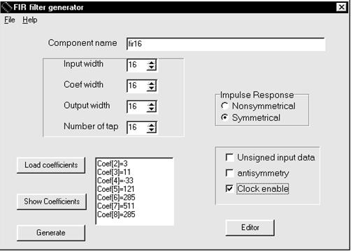
The generator is implemented as command line driven application as well. The customer can exchange the following parameters:
- coefficient set which is given as decimal, octal, hexadecimal, binary integers or real numbers;
- input data width from 4 to 24 bits;
- coefficient width from 4 to 24 bits;
- number of taps from 4 to 100;
- symmetric (SRBM), non-symmetric (NSRBM), and negative symmetric filters;
- output precision up to full precision;
- 2’s complement input data or unsigned input data;
- the speed slow down which is provided by the control of the Clock Enable signal.
The regulated maximum parameters are really unlimited. The mentioned above parameter limits are set as practical limits.
4. EXPERIMENTAL RESULTS
A set of FIR filters were generated by the new core generator and implemented in Xilinx FPGAs using Foundation 3.1. synthesis and implementation tool. The impulse responses were selected as real ones which represent the low pass and band pass filters with sharp frequency response characteristics and 60-70 db suppression rate. Some results for input and output data width 16, coefficient width 16, and symmetrical impulse characteristic are shown in the following table. The results of the Xilinx FIR PDA core generator are shown in the last row of the table for comparison.
| Filter type | Device type | Number of taps, K |
Hardware volume, CLB (slices) |
Maximum sampling frequency, MHz |
| SRBM | VirtexE-8 | 20 | 1022 | 212 |
| SRBM | VirtexE-8 | 99 | 5151 | 208 |
| SRBM | XC4000XV-07 | 20 | 1090 | 60 |
| SPDA | XC4000XV-07 | 20 | 1457 | 50 |
The table analysis shows that the resulting filter structures have the high throughput, minimized hardware, low hardware volume increase and low sampling frequency degradation when the filter complexity increases.
5. CONCLUSION
Finite impulse response (FIR) filters
REFERENCES
[1] Parallel Distributed Arithmetic FIR filter. Product Specification. Available at www.xilinx.com. Feb.8.1988.
[2] Peled A., Liu B. A New Hardware Realization of Digital Filters. IEEE Trans. on Acoustic Signal, Speech Processing, V.ASSP-22, June, 1974.
[3] Mintzer L. FIR filters with the Xilinx FPGA. FPGA’92, ACM/SIGDA Workshop on FPGAs, 1992, pp. 129-134.
[4] Goslin G.R. A Guide to Using Field Programmable Gate Arrays (FPGAs) for Application-Specific Digital Signal Processing Performance. Available at www.xilinx.com. 1995.
[5] Kanevski Ju.S., Nekrasov B.A., Sergyienko A.M. Issues of High-Performance FFT Procesor Implementation. (In Rusian). Upravlajustshie Systemy i Mashiny, 1986. №4, pp.60-63.
[6] Chapman K. Constant Coefficient Multipliers for the XC4000E. Application Note. Available at www.xilinx.com. December 11, 1996.
[7] Kaniewski J., Berezowski R., Gretkowski D., Maslennikov O., Soltan P. Modele VHDL filtrov FIR przeznaczonych do realizaciji w ukladach FPGA. Materialy III Krajowej Konferencji Naukowej “Reprogramowalne uklady cyfrowe”, RUC’2000, Szczecin (Poland), 10-11 Kwietnia 2000. pp.269-276.